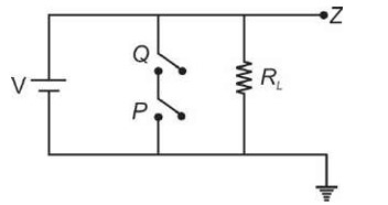
The logic gate realised from the circuit as shown in figure is (P and Q are inputs and Z is output)
The logic gate realised from the circuit as shown in figure is (P and Q are inputs and Z is output)
Similar Questions for you
Not really. The electric dipole moment vector directs or points from the negative charge to the positive charge. But the electric field lines that a dipole creates will point away from the positive and move to the negative charge.
Yes, the cube, which is a closed surface containing only one electric dipole will make electric flux zero. This follows Gauss's Law when the total charge inside it is zero. The field lines entering the surface will exit, and that would result in zero net flux.
The magnitude of each charge and the distance that separates them.
Gauss Law is only concerned with the total enclosed charge that finally tells us the total flux. The charges outside may change field patterns. They not affect the total flux. It's actually incorrect to assume the field due to the external charges should also affect the flux through the Gaussian sur
Gauss Law does not directly give the electric field in all cases. It can only be used in calculations for symmetrical surfaces: spherical, cylindrical, or planar.
Taking an Exam? Selecting a College?
Get authentic answers from experts, students and alumni that you won't find anywhere else.
On Shiksha, get access to
Learn more about...

Physics Ncert Solutions Class 12th 2023
View Exam DetailsMost viewed information
SummaryDidn't find the answer you were looking for?
Search from Shiksha's 1 lakh+ Topics
Ask Current Students, Alumni & our Experts
Have a question related to your career & education?
See what others like you are asking & answering


