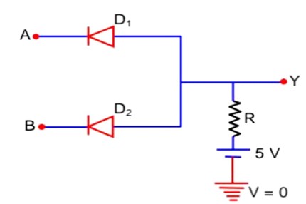
In the circuit, the logical value of A = 1 or B = 1 when potential at A or B is 5 V and the logical value of A = 0 or B = 0 when potential at A or B is 0 V. The truth table of the given circuit will be:


Option 1 - <p><span class="mathml" contenteditable="false"> <math> <mrow> <mtable> <mtr columnalign="center"> <mtd columnalign="center"> <mi>A</mi> </mtd> <mtd columnalign="center"> <mi>B</mi> </mtd> <mtd columnalign="center"> <mi>Y</mi> </mtd> <mtd columnalign="center"> <mn>0</mn> </mtd> <mtd columnalign="center"> <mn>0</mn> </mtd> </mtr> <mtr columnalign="center"> <mtd columnalign="center"> <mn>0</mn> </mtd> <mtd columnalign="center"> <mn>1</mn> </mtd> <mtd columnalign="center"> <mn>0</mn> </mtd> <mtd columnalign="center"> <mn>0</mn> </mtd> <mtd columnalign="center"> <mn>0</mn> </mtd> </mtr> <mtr columnalign="center"> <mtd columnalign="center"> <mn>1</mn> </mtd> <mtd columnalign="center"> <mn>0</mn> </mtd> <mtd columnalign="center"> <mn>1</mn> </mtd> <mtd columnalign="center"> <mn>1</mn> </mtd> <mtd columnalign="center"> <mn>1</mn> </mtd> </mtr> </mtable> </mrow> </math> </span></p>
Option 2 - <p><span class="mathml" contenteditable="false"> <math> <mrow> <mtable> <mtr columnalign="center"> <mtd columnalign="center"> <mi>A</mi> </mtd> <mtd columnalign="center"> <mi>B</mi> </mtd> <mtd columnalign="center"> <mi>Y</mi> </mtd> <mtd columnalign="center"> <mn>0</mn> </mtd> <mtd columnalign="center"> <mn>0</mn> </mtd> </mtr> <mtr columnalign="center"> <mtd columnalign="center"> <mn>0</mn> </mtd> <mtd columnalign="center"> <mn>1</mn> </mtd> <mtd columnalign="center"> <mn>0</mn> </mtd> <mtd columnalign="center"> <mn>1</mn> </mtd> <mtd columnalign="center"> <mn>0</mn> </mtd> </mtr> <mtr columnalign="center"> <mtd columnalign="center"> <mn>1</mn> </mtd> <mtd columnalign="center"> <mn>1</mn> </mtd> <mtd columnalign="center"> <mn>1</mn> </mtd> <mtd columnalign="center"> <mn>1</mn> </mtd> <mtd columnalign="center"> <mn>1</mn> </mtd> </mtr> </mtable> </mrow> </math> </span></p>
Option 3 - <p><span class="mathml" contenteditable="false"> <math> <mrow> <mtable> <mtr columnalign="center"> <mtd columnalign="center"> <mi>A</mi> </mtd> <mtd columnalign="center"> <mi>B</mi> </mtd> <mtd columnalign="center"> <mi>Y</mi> </mtd> <mtd columnalign="center"> <mn>0</mn> </mtd> <mtd columnalign="center"> <mn>0</mn> </mtd> </mtr> <mtr columnalign="center"> <mtd columnalign="center"> <mn>0</mn> </mtd> <mtd columnalign="center"> <mn>1</mn> </mtd> <mtd columnalign="center"> <mn>0</mn> </mtd> <mtd columnalign="center"> <mn>0</mn> </mtd> <mtd columnalign="center"> <mn>0</mn> </mtd> </mtr> <mtr columnalign="center"> <mtd columnalign="center"> <mn>1</mn> </mtd> <mtd columnalign="center"> <mn>0</mn> </mtd> <mtd columnalign="center"> <mn>1</mn> </mtd> <mtd columnalign="center"> <mn>1</mn> </mtd> <mtd columnalign="center"> <mn>0</mn> </mtd> </mtr> </mtable> </mrow> </math> </span></p>
Option 4 - <p><span class="mathml" contenteditable="false"> <math> <mrow> <mtable> <mtr columnalign="center"> <mtd columnalign="center"> <mi>A</mi> </mtd> <mtd columnalign="center"> <mi>B</mi> </mtd> <mtd columnalign="center"> <mi>C</mi> </mtd> <mtd columnalign="center"> <mn>0</mn> </mtd> <mtd columnalign="center"> <mn>0</mn> </mtd> </mtr> <mtr columnalign="center"> <mtd columnalign="center"> <mn>1</mn> </mtd> <mtd columnalign="center"> <mn>1</mn> </mtd> <mtd columnalign="center"> <mn>0</mn> </mtd> <mtd columnalign="center"> <mn>1</mn> </mtd> <mtd columnalign="center"> <mn>0</mn> </mtd> </mtr> <mtr columnalign="center"> <mtd columnalign="center"> <mn>1</mn> </mtd> <mtd columnalign="center"> <mn>1</mn> </mtd> <mtd columnalign="center"> <mn>1</mn> </mtd> <mtd columnalign="center"> <mn>1</mn> </mtd> <mtd columnalign="center"> <mn>0</mn> </mtd> </mtr> </mtable> </mrow> </math> </span></p>
47 Views|Posted 6 months ago
Asked by Shiksha User
1 Answer
V
6 months ago
Correct Option - 1
Detailed Solution:

When both A and B have logical value 'l' both diode are reverse bias and current will flow in resistor hence output will be 5 volt i.e. logical value '1'.

In all other case conduction will take place hence output will be zero value i.e. logical value 'o'.

So truth table is

A            B            Y

...Read more

Thumbs Up IconUpvote Thumbs Down Icon

Similar Questions for you

Here  Δ V c = 0 . 5 V , Δ i c = 0 . 0 5 m A = 0 . 0 5 × 1 0 3 A

Output resistance is given by

R o u t = Δ V c Δ i c = 0 . 5 0 . 5 × 1 0 3 = 1 0 4 Ω = 1 0 k Ω .

...Read more

i b = 5 0 . 7 8 . 6 = 0 . 5 m A

I c = β I b = 1 0 0 × 0 . 5   m A

By using 

V C E = V C C I C R L = 1 8 5 0 × 1 0 3 × 1 0 0 = 1 3   V

Photodiode operate in reverse bias. The photocurrent increases initially and saturates fi

Taking an Exam? Selecting a College?

Get authentic answers from experts, students and alumni that you won't find anywhere else.

On Shiksha, get access to

66K
Colleges
|
1.2K
Exams
|
6.9L
Reviews
|
1.8M
Answers

Learn more about...

Physics Semiconductor Devices 2025

Physics Semiconductor Devices 2025

View Exam Details

Most viewed information

Summary

Share Your College Life Experience

Didn't find the answer you were looking for?

Search from Shiksha's 1 lakh+ Topics

or

Ask Current Students, Alumni & our Experts

Have a question related to your career & education?

or

See what others like you are asking & answering