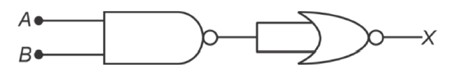
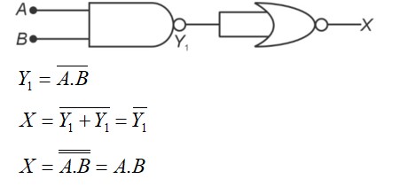
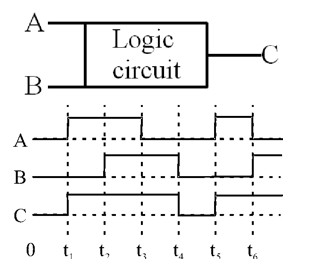
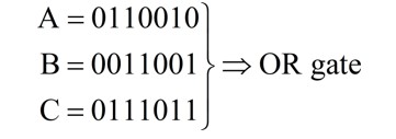
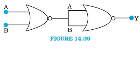
14.14 Write the truth table for circuit given in Fig. 14.39 below consisting of NOR gates and identify the logic operation (OR, AND, NOT) which this circuit is performing.
(Hint: A = 0, B = 1 then A and B inputs of second NOR gate will be 0 and hence Y=1. Similarly work out the values of Y for other combinations of A and B. Compare with the truth table of OR, AND, NOT gates and find the correct one.)
14.14 A and B are the inputs of the given circuit. The output of the first NOR gate is + . It can be observed from the following figure that the inputs of the second NOR gate become the output of the first one.


 Upvote