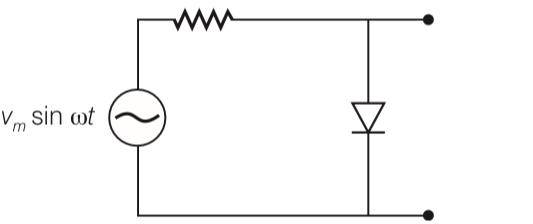
The output of the given circuit in figure is given below.

(a) Would be zero at all times
(b) Would be like a half wave rectifier with positive cycles in output
(c) Would be like a half wave rectifier with negative cycles in output
(d) Would be like that of a full wave rectifier

21 Views|Posted 9 months ago
Asked by Shiksha User
1 Answer
A
9 months ago

This is a Multiple Choice Questions as classified in NCERT Exemplar

Answer- c

Explanation- due to forward biasing the diffusion current in the circuit is very high and resistance in the circuit is very low. Thus voltage across pn junction is very low but in case of reverse biasing diffusion current ve

...Read more

Thumbs Up IconUpvote Thumbs Down Icon

Similar Questions for you

Taking an Exam? Selecting a College?

Get authentic answers from experts, students and alumni that you won't find anywhere else.

On Shiksha, get access to

66K
Colleges
|
1.2K
Exams
|
6.9L
Reviews
|
1.8M
Answers

Learn more about...

Physics NCERT Exemplar Solutions Class 12th Chapter Fourteen 2025

Physics NCERT Exemplar Solutions Class 12th Chapter Fourteen 2025

View Exam Details

Most viewed information

Summary

Share Your College Life Experience

Didn't find the answer you were looking for?

Search from Shiksha's 1 lakh+ Topics

or

Ask Current Students, Alumni & our Experts

Have a question related to your career & education?

or

See what others like you are asking & answering